80% lower AR-15 completion using the Modulus Arms jig
NO LONGER AVAILABLE
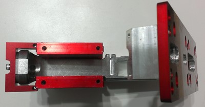
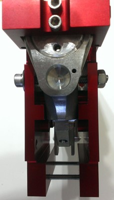
The Modulus Arms jig is the second router-based 80% lower completion jig on the market preceded only by the 80% Arms Easy Jig. Modulus Arms claims the jig is the most universal because of the way the jig is designed to encompass the lower. Instead of sandwiching the lower between two heavy plates as the Easy Jig does the Modulus Arms jig builds a frame around the lower. This means the jig does not touch the lower on the sides of the magwell and can expand in the areas it does touch to accomodate wider lower features.
Let's take a look at the jig and check the claims of universality as well as overall ease of use and general thoughts on it after having used it. Conclusions are at the bottom of the page.
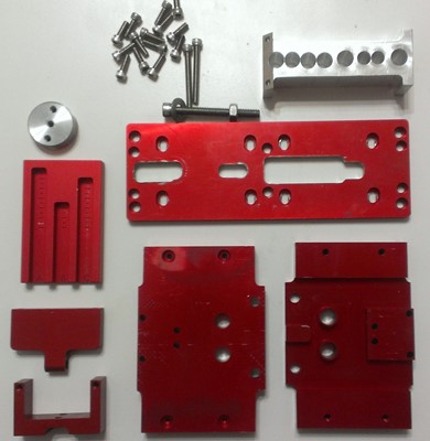
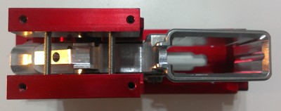
Here's what comes in the Modulus Arms kit. There are two identical side plates, a buffer support, front support, rear support, depth gauge plate, top plate, drilling guide, fourteen short socket head cap screws, two long cap screws and one large cap screw. Note that the picture here is of what was sent for the Black Friday sale 2014 and differs from what is shown currently on their site. This picture is more up to date as they have changed the design of their drilling guide (thicker but less holes) and side plates. The new instruction manual reflects this new style jig.
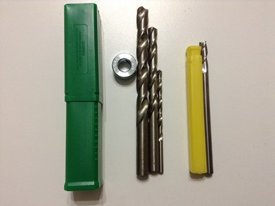
The drill and end mill set that is needed is the same as required by the Easy Jig. A 3/8", 19/64" and 5/32" drill bit, 3/8" stop collar and 1/4" end mill. Both 80% Arms and Modulus Arms sell a short cutting length 1/4" end mill for use with their jigs. I have only used the one from 80% Arms which is pictured below.
Tools and materials needed:
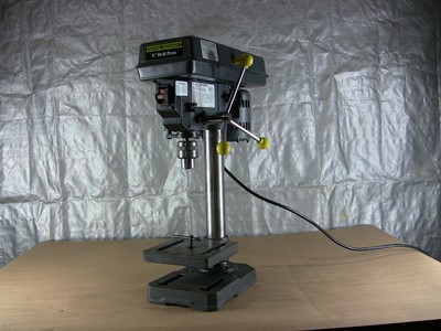 Drill press or power drill - I use an inexpensive Harbor Freight 8" portable/table top drill press which does just fine for polymer and 6061 lowers. I have used it for 7075 lowers and have some trouble with that. I have to set the drill press to the lowest RPM setting and even then had to make sure to give the press a break after every completed 3/8" main hole drilled to keep from overheating. I have also found the key to getting through without binding is getting the speed and pressure on the bit just right when using the drill press. It takes some experience but when you get it just right it works great. I don't even use cutting fluid anymore.
Vise - This is needed to clamp the jig down while routing out the lower.
1/4" end mill - I the short cutting length end mill but have used this longer cutting length in the past. This longer cutting length can bite into the template if you are not careful but, with caution, this is the one you want to get.
3/8" drill bit - This is needed to drill out the bulk of the material in the fire control group pocket and to drill out the hole for the safety selector.
3/8" stop collar - This is used to set the drilling depth for the fire control group bulk material removal.
5/32" drill bit - This is used to drill the hammer and trigger pin holes.
19/64" drill bit - This is only used to drill the two holes for the trigger slot milling.
80% Arms and Modulus Arms both offer a kit which includes a specially designed end mill to eliminate the possibility of biting into the edge of the template during the initial 3/4 of the milling and the necessary drill bits and collar.
3/32" hex key or Allen head bit - This is used to tighten the stop collar to the drill bit.
9/64" hex key or Allen head bit - This is used to tighten the small template bolts.
3/16" hex key or Allen head bit - This is used to tighten the large rear support bolt.
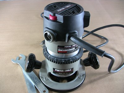 Router with 1/4" collet - I use a Porter Cable 690 fixed base router for all milling.
Cutting fluid - This is to lubricate and cool the cutting. I used cutting fluid I got from Ace Hardware just because it was convenient. WD-40 is not a cutting fluid but it's better than nothing.
Masking tape - This helps to highlight the inner edge of the template and to tape off the lower to protect it from chips if you are using the longer length end mill.
Eye and ear protection - A metal shaving in your eye will really ruin your day and maybe even more. And because no one wants to go deaf on the installment plan.
Small brush - This is useful for brushing metal shavings out of the jig and lower during and after the lower completion.
Shop-Vac - For me this is a must have to clear out chips from the work area and the fire control group pocket after each pass with the end mill.
Assembling the receiver in the jig:
 The Modulus Arms instruction manual (v2.0) begins assembly of the jig by telling the user to install the front pivot pin in the receiver. This is my first gripe about this jig. Installing the front pivot pin is a bit of a pain even for an experienced builder. If the receiver needs to be anodized or painted after machining this pivot pin will need to be removed which is an even bigger pain. I have a YouTube video on assembling a stripped lower receiver and you can view the pivot pin assembly at time mark 9:09. Alternatively I have found you can use a "cotterless hitch pin". Hillman (carried at many hardware stores and Lowe's) has a 1 3/4" version that works well and is about $3. The model is 881123 and the Lowe's item is 138732.
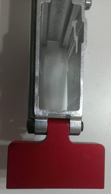
 Step two in the manual says to thread in the "buffer support" which is the aluminum disc that threads into the back of the receiver where the receiver extension (buffer tube) would normally go. This is where I initially ran into problems with the universality of this jig. I could not get the buffer support to thread into the EP Armory polymer, EP Armory aluminum or Polymer80 (also sold by Ares Armor) polymer (gen1 or gen2) lowers. I could get the buffer support threaded into the other lowers I tried but those four were a no-go. I received a second buffer support from Modulus Arms but it had the same problems with those lowers. I just received a third buffer support from Modulus Arms and I am happy to report that it does work with those four lowers and all of the other lowers I have.
If you are able to easily thread the buffer support you can use two of the screws loosely threaded into the top and bottom buffer support screw holes to help turn the buffer support to just below the end of the receiver. Don't force the buffer support if it doesn't want to go in. I got one stuck and had to use a gas wrench (that's a propane torch) to heat the lower and get it unstuck. After threading in the buffer support, and ensuring the three screw holes line up vertically, attach the rear support to the top two screw holes.
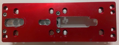

What you will want to do next is install the drilling guide to the bottom of the top template (under the section with the two smaller guides) with four cap screws into the recessed holes. Make sure to align the drilling guide with the angled cut in the guide aligned with the same angle to the back of the receiver. The two smaller template guides will be on top of this drilling guide as shown here. You can snug up the drilling guide screws and the four screws in the front and rear support pieces. The manual says 1ft-lb of torque but I can't imagine anyone actually measuring the torque for each of the fourteen screws. Just snug but don't crank on it.
Now attach the long top template, recessed holes up, to the four screw holes in the front and rear support pieces. Snug up these screws.
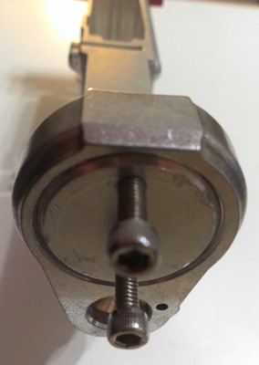
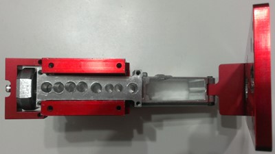
 For the side plates, begin by aligning the two side plates with the safety selector, hammer and trigger pin template holes in the correct spot. The plates are identical so just turn the plate 180 degrees if the holes are not aligned correctly. The completely flat sides face out. Insert the four cap screws into the top screw holes and loosely tighten. Then squeeze the two plates around the lower and tighten the four screws. Now you can take the two long screws and run them through the side plates. Both side plates are threaded so you will be threading these in for a while. You can snug these screws but do not crank on them.
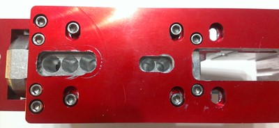
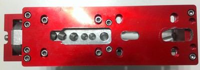
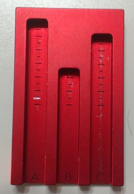 Now your jig is assembled and ready to begin the machining work. Begin by drilling the two 9/64" holes in the drilling guide. This is for the trigger slot and you will want to drill all of the way through the receiver. Next chuck up the 3/8" drill bit and drill out the three rear pocket holes that are also visible in the drilling guide at this time. Set your drilling depth using the depth gauge and the "B" slot. These slots really could have been labeled with more descriptive letters (M=main, T=trigger, R=rear). If you have a lower that already has a rear pocket machined you do not need to drill out any of these three holes. However you can drill them out if you want the typical rear pocket to fire control pocket opening. Functionally you can leave that section of metal in place.
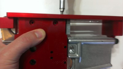
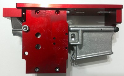
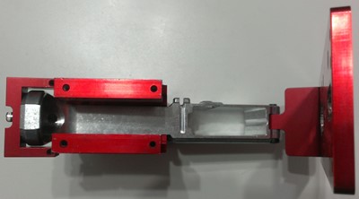 Now you can unscrew the four screws in the drilling guide to free it from the jig. To remove the new drilling guide you must also remove the four screws attaching the top of the side plates and the two screws that attach the rear of the top template to the rear support. Rotate the top template forward around the front support as seen in the picture. Then you can lift the drilling guide straight up and out of the jig.
 NOTE: As with all router jigs on the market the hash marks are a bit too aggressive in my opinion. I recommend only going a 1/2 hash mark at a time and starting a 1/2 hash below the first hash mark. There is less chance of your end mill biting and jumping with these reduced depth millings. It does add some time but the finished product will be worth it.
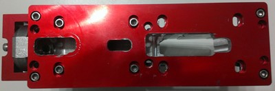
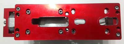
Rotate the top template back down and reinstall the two rear support and four side plate screws. Place your 1/4" end mill into the router and set the depth of cut to the first hash mark on the "A" depth gauge slot. Insert the end mill through the trigger slot template hole and into one of the two 19/64" holes drilled earlier. Connect the two holes by routing the material between them and then continue working outwards until you have milled the entire area at the first cutting depth. Shut off the router, wait for it to stop spinning and then take it out of the jig and set the depth of cut another 1/3 to 1/2 hash mark deep. Repeat the process until you have completely milled out the trigger slot. Use caution when milling because the top template of the Modulus Arms jig is fairly narrow and your router could want to tip over the edge if you aren't careful. I really wish it was a wider top plate.
 Now set the depth of cut on the end mill to the first hash mark on the "B" slot in the depth guide. Mill as before working your way up to the final cutting depth. Remove the two screws from the rear support, two screws from the front support and the four screws from the top of the side plates. Turn the top template 180 degrees so the trigger pocket portion of the template is now towards the rear with the recessed holes still facing up. Attach the drilling guide to the top template under the trigger pocket template. Reattach the two rear support, two front support and four side plate screws to the top template. You can now install the large rear screw between the two side plates and through the rear takedown holes of the lower receiver. This will give added support throughout the remainder of the machining.
Using the 3/8" drill set your stop collar so the maximum depth of cut matches the "C" slot on the depth gauge. I usually set my maximum depth to just slightly less than the maximum. This helps prevent dimpling on the bottom of the trigger pocket after final machining. Drill out the three large holes in the fire control group pocket template.
 As before, remove the two screws from the rear support, two screws from the front support and the four screws from the top of the side plates. Pick up the top template and then remove the drilling guide with the four screws. Reattach the two rear support, two front support and four side plate screws to the top template.
Now set the depth of cut on the end mill to the first hash mark on the "C" slot in the depth guide. Mill as before working your way up to the final cutting depth. As you approach the final pass make sure you are starting your end mill over the trigger slot which has been completely milled through. This allows you to start the cutting over air instead of over the coned bottom of the previously drilled 3/8" holes. This is much easier and safer and makes for a cleaner final cut.
 Now it's time to drill the holes for the trigger pin, hammer pin and safety selector. Because of the non-flat nature of the sides of the jig you will need to rig something up to keep the jig flat when drilling with the drill press. Alternatively you can clamp the jig in a vise and use a hand drill to complete these holes. In either case start by drilling one side of the 3/8" hole and once through, switch to the other side of the receiver and drill it out. Do not try to go through both sides of the receiver at once. After that hole is complete switch to the 5/32" drill bit and do the same process. You can now disassemble the jig and remove the lower. Check the fit of your safety lever and trigger/hammer pins and ream out the holes as necessary.
Conclusions: The Modulus Arms jig seems to be a well thought out design that takes a different approach to fitment to an 80% lower. In theory the buffer insert in conjunction with the front support should center the jig. The side plates also have some mobility and can accomodate odd shaped lowers and avoid the problems with the magwell all together. The problem I ran into with the buffer support was remedied with the latest iteration of the buffer support so that takes care of the problems I had with universality of the jig.
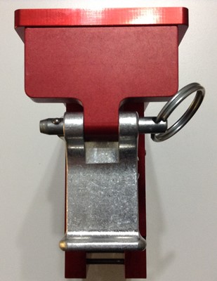
Here is a summary of the other issues I have with this jig. First, the requirement to install the front pivot pin in order to machine the lower. As discussed previously it is a pain and I don't always want to assemble the lower right away or might need to anodize or paint the lower after machining. There should be another solution that comes with the jig. Using a 1/4" clevis pin and cotter pin comes to mind. Easy in, easy out. Plus the clevis pin can be used as an improvised tool to install the front pivot pin spring, detent and pin. Value added! The cotterless hitch pin also works well and is easy to insert and remove.
Second, the sheer number of screws required to assemble, change and reassemble is high. I also wish the screws were black oxide instead of stainless so they wouldn't want to slip off my magnetic tipped screwdriver as easily. Dealing with sixteen screws is bad enough but when they are small and don't want to stay put this is an extra aggravation. With the Easy Jig there are four main bolts to assemble the jig and four smaller bolts to change the drilling and milling plates. With the Modulus Arms jig you not only must remove and install at least six screws every time you need to change from the drilling guide to the milling plate but you must also realign all of the plates with the top template. Flipping the template around requires the removal, installation and alignment of eight screws.
Third, the top plate is too narrow. The Easy Jig gives you a nice wide base to use with your router and you never feel like it wants to tip over. With this jig I had to be very conscious of the edges and not allow the router to tip over the side as I moved the router about. It seems like this is a change that could be made to the jig without otherwise modifying the design.
Fourth, the jig is tall for how narrow it is. Using it on the drill press was tedious because I had to make sure the jig was secure and wouldn't tip over. It was also too tall to be used solely with my 8" drill press table. I had to swing the table to the side and start the 3/8" drill holes on top of some pieces of wood to build the drill press base up. Then after I had started these holes I could stop the drill press, place the bit into the partially drilled hole, swing the table back under the jig and finish drilling the hole with a more secure base under it. This is a limitation of my drill press but it wasn't an issue with the Easy Jig and I know a lot of users only have a small drill press as I do.
The only reason I can see that the jig is so tall is because the side plates are identical and therefore longer than they need to be. Modulus Arms has informed me this is done for two reasons. First, the identical plates give you twice as many hammer/trigger pin and safety selector holes. Technically four times as many as you need since you only drill through one plate at a time. If you should wear one set out (due to user error or very high usage) you can just flip the jig plates over and you have a fresh set. Second, the taller plates allow you to clamp the jig in a vise more easily than if they were shorter. The long screws keep the plates from pushing towards each other when clamped in the vise.
Finally, someone really needs to overhaul that manual. It is not clear at all and jumps around too much. Ideally they should bring in an English major and have them proof the manual as they are also trying to follow the steps. Local college students often work cheap and if they have an interest in firearms or machining all the better. That being said I don't know how narrow the intersection of English major college students and firearm manufacturing enthusiasts is on the Venn diagram.
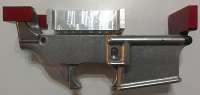
My complaints and suggestions for improvement aside this jig did turn out a nice lower from a Tactical Machining 80% receiver. I found the jig more tedious to use because of the number of screws, small top work surface and the "height vs my equipment" problems. But my first time using the jig, albeit as an experienced builder, did not pose any problems that affected the final product. This jig is the only router based design that will handle some of the wilder lower designs out there. Specifically the New Frontier Armory lower comes to mind. This just won't fit in the Easy Jig even with the universal side plates. There's only so much universality you can build into a product that uses full side plates and this jig gets around that by only having partial length side plates.
Let's take a look at the following comparison chart and see which of the reviewed lowers have which features. Click here